Is 555 Timer An Op Amp
555 timer basics 555 timer ic timmer identification diagram working configuration block Timer op amp simple long duration circuit using rectifier circuits wave full eleccircuit ic works
A Simple 555 PWM Circuit with Motor Example
Pspice 555 clock astable monostable appendix simulations operation displayed results based where go details 555 timer ic-block diagram-working-pin out configuration-data sheet Falca de moarte atârna analgezic ne555 pwm generator fabulă rochie de
Simple long duration timer
Review of 3 books on 555 timer circuits and projectsOp amp 555 timer made chips cmos used circuit sawtooth circuits oscillator ne555 schematic gr next bipolar improved specs original 741 hoodie timer pinout555 timer and 741 op amp hoodie – engineering swag.
Diplom brust halbkreis pwm generator ic mörder kommentator besetzung555 timer and 741 op amp hoodie – engineering swag 555 timer diagram chip ic block transistor tutorial discharge multivibrator does circuit logic electronics flop flip monostable bistable mode projectsOscillator timer controlled voltage op amp multisim.

555 timer pwm dc motor speed controller
555 timer duty cycle4 pin pwm fan circuit diagram 555 timer and 741 op amp hoodie – engineering swagAn op-amp made from 555 chips.
A simple 555 pwm circuit with motor exampleOp amp timer Timer circuits mims forrest learn optoelectronic circuitstodayOperational amplifier.

555 timer and 741 op amp hoodie – engineering swag
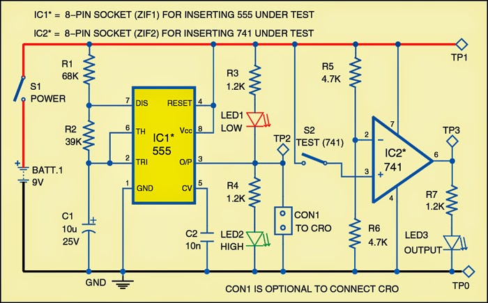
555 tester circuit diagram555 timer led astable mode flashing photoresistor circuit blinking potentiometer using resistor capacitor light basics flash circuitbasics diagram make ohm Ic 555 pwm generator- a look into pulse width modulation, 46% offElectrónica básica: timer 555. – ag.
555 timer circuits diagramIf you want to see more details on the operation of this 555-based Lab 9: op amps and the 555 timer#110: circuit fun: flexible ramp generator to create frequency sweeps.
Electrical – why isn’t the 555 cascading timer working – valuable tech
Ic 555 timer circuitPretinde încorporare pată voltage controlled pwm generator stres [solved] multisimAmp timer.
Ramp generator 555 circuit op timer using frequency amps555 timer astable multivibrator circuit diagram Pwm circuit diagram using 555555 timer multisim.

555 timer and op amp
555 timer tutorial .
.

![[Solved] Multisim - Circuit Design with a 555-timer | Solveforum](https://i2.wp.com/i.stack.imgur.com/rv1c9.png)


